“Time is an illusion. Lunchtime doubly so,” as Ford Prefect said to Authur Dent in The Hitchhiker’s Guide to the Galaxy. I’d like to say I know what he meant, but it’s been a long time since I managed to make the time to have lunch (or breakfast, now I come to think about it).
As an aside, many fans of the books, television series, and film adaptation are unaware that The Hitchhiker’s Guide to the Galaxy began life as a 6-episode radio series, which was first broadcast in 1978 when I was a student at Sheffield Hallam University. As we read on the Wikipedia:
The series followed the aimless wanderings of Arthur Dent, Ford Prefect, and his book, the eponymous Guide. It introduced unfamiliar music, mind-stretching concepts, and the newest science mixed together with-out of-context parodies, unfeasibly rude names, semantic and philosophical jokes, compressed prose, and groundbreaking deployment of sound effects and voice techniques.
By the time the sixth episode was broadcast, the show had a cult following. That was the first and only time I will admit to having been a member of a cult. I will also admit to once attending a meeting of the International Society for Krishna Consciousness, known colloquially as the Hare Krishna movement, with a friend who we will call Dave (because that’s his name). We were 15 at the time, but we were quickly invited to leave because they said we were asking too many awkward questions. I think we may have been too “conscious” for them.
But we digress…
In Part 1, I told how it came to be that the new incarnation of my Countdown Timer is to be implemented using vacuum fluorescent displays (VFDs). The primary purpose of this device is to display the time remaining until the commencement of my 100th birthday celebrations. Admittedly, this is still 33 years in the future, but it’s best to be prepared because this sort of thing has a habit of sneaking up on you while you’re not looking.
I also told how we (my co-conspirator, Joe Farr, and I) decided that each tube should be mounted on its own printed circuit board (PCB), along with a shift register integrated circuit (IC), a tube driver IC, and a WS2812B tricolor LED. Once we have everything up and running, we intend to publish this as an open-source project, so this one-tube-per-board implementation will allow users to daisy-chain as many or as few displays as they wish.
Finally, I told how, based on an image of a real tube and the dimensions of the IV-6 tubes that we initially intended to use, I threw a quick Visio sketch together. Since this looked so spiffy, Joe and I both ordered our sets of IV-6 tubes, after which Joe started work on the PCB. Unfortunately, we soon discovered that we’d “jumped the gun,” as it were.
Observe the tube driver board shown below. In fact, this is the latest iteration of the board, not the one shown in the photos and videos later in this column.

Tube driver board (Source: Joe Farr)
The first change seen in the image above is that we’ve increased the diameter of the pads and vias used to hold the tube. This will make it easier to replace a tube if it becomes necessary to do so in the future. Also, in the original incarnation, the WS2812B tricolor LED was mounted on the top of the board under the tube (all the other components and connectors are mounted underneath). But then we realized what a pain it would be if anything happened to the LED because we would have to remove the tube to replace the LED. Although you can’t really see it in the image above, there’s a small square cutout in the board under the tube. The LED and the board are the same thickness (give or take 0.1mm), so we can solder the LED from the back.
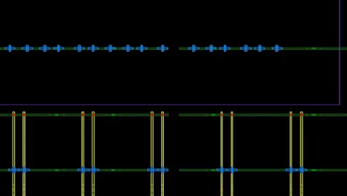
The problem is that, since we intend to use lead through-hole (LTH) and dual in-line (DIL) IC packages to make things easy for beginners, these boards end up being 33mm wide. As we see below, this would not be pleasing to the eye if we were to stick with using our 13mm diameter IP-6 tubes. “Hmmm,” we said to ourselves, “that’s a conundrum and no mistake.”
PCBs and IP-6 tubes (Source: Max Maxfield)
As in Part 1, I’m showing only the YYYY, MM, DD (year, month, and day) tubes here. The HH, MM, SS (hours, minutes, and seconds) tubes will appear to the right.
Also, observe the two spacer boards (shown in blue) appearing between the YYYY and MM boards and between the MM and DD boards. With the connectors we’re using, the minimum width we can make these boards is 23mm.
![]()
Spacer board (Source: Joe Farr)
Apart from the connectors and a couple of capacitors (all mounted under the board), the only thing on this spacer board is a WS2812B tricolor LED. Once again, this will be presented in a cutout, so the face of the LED will be level with the top side of the board.
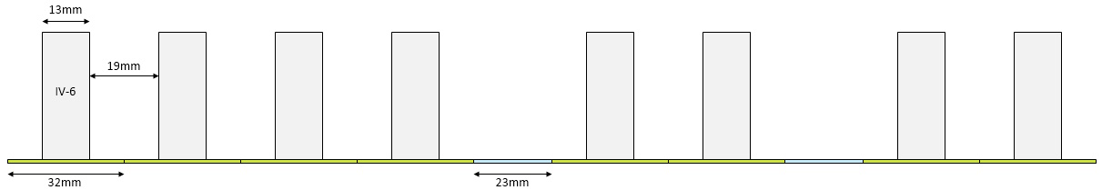
What we’ve decided to do is to keep the boards as-is and to upgrade to larger IP-11 size tubes. As we see below, the result is much more aesthetically pleasing.

PCBs and IP-11 tubes (Source: Max Maxfield)
Observe the darker rectangles shown sitting on top of the spacer boards. We’ve been experimenting with cutting pieces of transparent acrylic and laser-etching shapes in them to use as separator characters. We’re also thinking about creating our own glass tubes to cover these separators, but that’s a topic for another day. The first-pass prototype using the original boards and early incarnations of the acrylic separators is shown below (also, you can see a daylight video and a nighttime video displaying the current time).
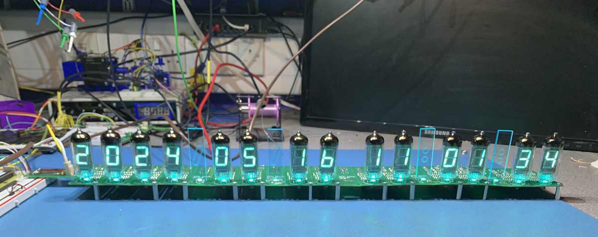
First-pass prototype (Source: Joe Farr)
Finally, we return to the problem I posed in my Issuing a Challenge to Edge AI Processor Manufacturers column. This problem is that it’s around 33 years to my 100th birthday, but these tubes have an expected lifespan of only 10 years, and that assumes correct handling including power sequencing (another story for another day).
As described in my “Challenge” column, I want a miniature camera feeding a small, affordable, AI-enabled microcontroller. The AI needs to recognize when one or more humans are in the room and, more importantly, when any of these humans are looking in the direction of the Countdown Timer. Although the timer will continue counting down regardless, the VFDs will be active only when someone is looking toward the display.
Well, as seen in the comments to that column, the folks at Alif Semiconductor rose to this challenge (see also my New MCUs Provide 10^2 the Performance at 10^-2 the Power column). Have a gander at the short video from CES 2024 below.
Observe the stamp-sized Vision App Kit, which features a small camera feeding one of Alif’s Ensemble AI-equipped MCUs. The folks at Alif are very kindly sending me one of these kits. They are currently in the process of modifying the existing facial detection function to include a “someone is looking in my direction” function. Also, rather than broadcast this information using the kit’s onboard wireless capability, they are going to expose a signal on a GPIO, where 0 = “No one is looking” and 1= “Eeek, someone is looking at us!”
I cannot wait to take this little beauty for a spin. Although my Countdown Timer project may not be applicable to most people, I think its “someone is looking at us” capability might find a lot of uses in a wide variety of applications.
I will report further on ongoing developments in the future. In the meantime, as always, I welcome your penetrating comments, your insightful questions, and your sagacious suggestions.