

We recently took a look at one side of vibration: the side that uses it to diagnose nascent illness in manufacturing equipment. And I hinted at a second side, which is what we’ll look at today. The previous discussion was about detecting and decoding vibrations. This one will be about leveraging vibration to harvest energy.
Yes, not a new concept, and we’ve talked about it before, but our prior focus has largely been on piezoelectric solutions. Not so today.
Our focus this time will be on a joint project involving an energy harvester from OMRON and the rest of the system from Imec. We’ll start with the MEMS harvester and then look at how that energy gets managed.
Imec claims this as the first self-sufficient such system. I know that at ISSCC a few years ago, there was a presentation of the first self-sufficient harvester (also piezoelectric), and other folks have done self-sufficient nodes. But Imec says they’re the first to do a completely autonomous node consuming under 10 µW that included boot-up. But… I’m getting ahead of things here. (Just wanted to sort the bragging rights.)
In a perverse sort of feedback, what this means is that the power management IC (PMIC) is powered by its own output, which suggests challenges for that boot-up cycle.
But first, the harvester itself.
Presenting, live for your listening pleasure… The Electrets!
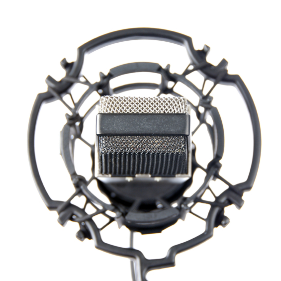
OMRON’s harvester uses a MEMS electret. Non-MEMS electrets have historically been used for microphones, but, as MEMS microphones continue to make advances against traditional electret microphones, I’ve had less and less incentive to learn what electrets really are. This project changed that.
An electret is the electrical analog of a permanent magnet. Imagine taking a capacitor, placing a voltage across it to polarize it, drawing charges to the two edges, and then somehow “freezing” the capacitor there. This would be an electret. Except that a material can naturally have this property; it doesn’t need to be created (the freezing thing was just a thought exercise for illustration – except that you really can make an electret this way by heating a dielectric within a strong e-field).
So an electret is a substance with a permanent dipole “built in.” Piezoelectrics need deformation to form a dipole; electrets don’t. Electrets have a surrounding electrostatic field in the way that a magnet has a surrounding magnetic field.
The following image shows how this can be leveraged in harvesting.
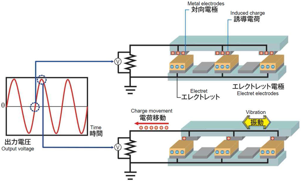
Image courtesy OMRON
The electret is shown attracting positive charges from the neighboring metal electrode across a gap. If that top plate moves relative to the bottom one, less of the electrode overlaps and is influenced by the electret, and so less charge is attracted. This movement of charge as the top plate moves creates a voltage that can do work.
As a quick aside, I have to confess that, while studying this topic, I kept having this nagging feeling that, somehow, charge conservation was being violated. After all, the electret is a dielectric – it can’t conduct charge. The metal can, of course, but then… where does it go? How does it get replaced?
I had to remind myself of two things.
- First, this is an AC system. Yes, when the plate moves one way, charge moves the other. But then the thing is going to come back and slide the other way, so on average, any charge “sent away” will come right back.
- The second, more subtle thing is that we (or, at least, I) have been lulled by the convenient simplification of the notion of “ground.” That’s because most of our systems are line-powered, and we get this infinite inflow of charge that then disappears, literally, into the ground. But a system like this (just like your cell phone) is a complete power circuit in itself. There is no “ground” that actually attaches to the ground (the figure above notwithstanding). With the flowing charges, it’s literally true that, what comes around goes around. No charge was created or destroyed in the making of this system.
So, up to this point, we have a way to generate an AC signal. Now we need to turn that into something useful. (The charge-loss issue nagged me with respect to the PMIC too… point 2 above still holds.)
And the handoff to PMIC…*
From here, we need to rectify the AC signal and turn it into something that can run a sensor node. One of the challenges here is voltage: harvesters generate 10s of volts (up to 60 in this case), and such voltages are generally not welcome on the power contacts of delicate silicon circuits. So the PMIC must bring this down to a friendlier 2.5 V.
The following diagram shows the whole system (with “ESH” being the harvester). CIN holds up to 60 V; COUT around 2.5 V.
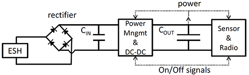
Image courtesy Imec
(To be clear, this circuit comes from a paper Imec did on a tire pressure measurement system that used a different harvester. But it still applies to this project as well.)
There are at least two critical ways in which power has been minimized in the PMIC. One is the use of sub-threshold design, which, while difficult, can have an extraordinary impact. The second is done through judicious use of sleep modes.
The power management measure-and-report sequence looks something like this:
- At the start of the cycle, a microcontroller (MCU), sensor subsystem, and radio are all asleep.
- The MCU wakes up and measures the output voltage; at this point, it’s run on a very slow 8-MHz external RC clock; just the bare minimum. The assumption is that we’ve passed the boot-up stage, and there’s enough power for this minimal step.
- If there’s not enough voltage to proceed, then it waits.
- If the voltage is OK, then the MCU turns on a 32-kHz clock and then goes to sleep while the crystal stabilizes. This is the longest part of the cycle.
- Once stable, the MCU wakes up and initiates the measurement by waking up the sensor; the MCU goes back to sleep while the measurement takes place.
- When the measurement is done, the sensor wakes up the MCU again; the MCU reads the data and puts the sensor back to sleep.
- The MCU then wakes the radio circuit up and goes back to sleep while the radio settles in.
- Once the radio has settled, it wakes the MCU back up.
- The MCU then sends the data to the radio circuit and goes back to sleep.
- The radio transmits the data, waking the MCU back up when it’s done.
- The MCU then shuts down the radio, goes to sleep, and the cycle repeats.
This can be summarized by the following image. I used a measured power graph from Imec and overlaid atop it a timeline of what’s on and off when for easy correlation.
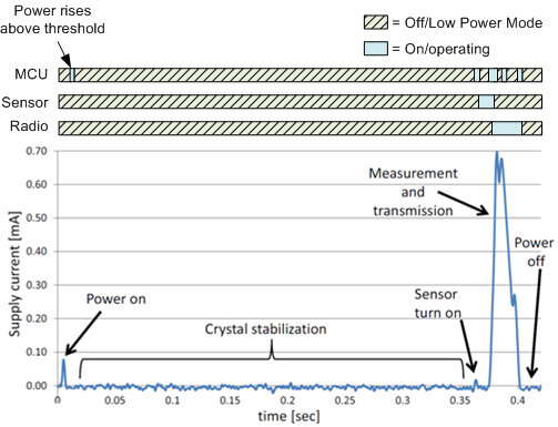
Annotated graph courtesy Imec
The PMIC itself dissipates less than 10 µW during full-up operation.
But then there’s startup. At that point, there’s not enough power to run the entire PMIC (much less the sensor node). So it goes into “direct charging” mode, where it simply squirrels away the charge on the cap until it has the necessary voltage to proceed further. During this time, the PMIC draws only 50 nA.
Once there’s enough power (2.2 V), then the system goes into “discontinuous mode” with maximum power point tracking (MPPT), which adjusts the conversion in real time for maximum efficiency.
There’s also a bit of hysteresis built in (although they didn’t call it that) when powering the sensor node. The sensor is disconnected during direct charging mode. Once the threshold is achieved, there’s a delay before the sensor is reconnected to make sure that attaching the sensor doesn’t suddenly drive the PMIC back into direct charging mode.
So that’s the essence of their system, leaving out, of course, the specifics of the conversion circuits. This unit needs no batteries for backup – chargeable or otherwise. That eliminates the need to change batteries (Imec suggests that even rechargeables may actually need replacing every couple of years). And there’s no environmental impact from battery materials.
*With apologies to readers not familiar with the US’s flavor of “football”… in fact, “handing” off would seem to have no logical place in a “foot” ball game…


How do you see this OMRON/Imec project comparing to other energy harvesting work being done?
Not fully MEMS–
While the electret is MEMS, the resonant springs are far less sophisticated. These springs are relatively large/meso-scale and metal (as you would find in a hardware store). They do allow for low resonant frequencies < 100 Hz to be obtained. But, these also limit size (currently 20 mm X 20 mm x ~7mm) and cost reduction possibilities that a true, fully MEMS device could achieve. Temperature limited– The temperature of the unit is limited to a maximum of 100 degrees Celsius. This is due to the organic materials used to create the electret electrode surfaces. This is an issue for high temperature applications, like can be found in an industrial environment. Power density limited– It is well known that capacitive vibrational energy harvesting (VEH) techniques have lower achievable power densities than piezoelectric or inductive VEH. This is due to that you cannot increase the charge Q on the electrode surface beyond a maximum point. The organic dielectric materials in this design allow for a decent amount of Q to be generated. But, the only way to increase this further is by increasing surface area, which lowers power density (or finding another material, which may be difficult). The maximum power currently achieved from the current configuration is 100 microWatts average AC, which post AC-DC conversion is ~70 microWatts DC using the IMEC designed electronics (kudos for the high conversion efficiency!) It is also well know that most wireless sensor nodes need an average of 100 microWatts DC or more (e.g. off-the-shelf Linear Tech/Dust Network WS nodes use 65-165 microWatts DC, depending upon duty-cycle). The bottom-line that this electret design is limited. That is unless you stack multiple units electrically together, which is something the Omron/IMEC team has shown can be done to achieve higher power or wider frequency bandwidth.
It sounds like, for the most part, you’re taking issue with the electret. If a different harvester were used with the same PMIC (assuming voltage compatibility), would that address the concerns?
While I don’t want to speak entirely on Imec’s behalf, my expectation is that this is a research project, not a commercial product, so I’m assuming refinements were it to go to market…