


I learn something new every day, which can be good news or bad news depending on what that thing happens to be. Thankfully, in the case of this column, I’m happy to report that I’ve learned something that’s both interesting and useful, which (sadly) isn’t always the case.
Before we start, just to make sure we’re all tap-dancing to the same skirl of the bagpipes, GNSS (Global Navigation Satellite System) is a broad term that generically refers to all satellite navigation systems worldwide. It includes multiple satellite constellations from different countries:
- GPS (United States)
- GLONASS (Russia)
- Galileo (European Union)
- BeiDou (China)
- QZSS (Japan, regional)
- NavIC (India, regional)
Meanwhile, GPS (Global Positioning System) is a specific satellite navigation system operated by the US Department of Defense. It consists of 30+ operational satellites in Medium Earth Orbit (MEO), it works worldwide, and it’s the most widely used GNSS system.
A GNSS receiver can use signals from multiple systems (e.g., GPS + Galileo + GLONASS), while a GPS-only receiver relies strictly on the US GPS network. GNSS provides improved accuracy and redundancy by using more satellites from different constellations.
We all like to know where we are (“why we are” is a more existential question). This is true of both people and autonomous machines like robots and drones. I come from the days before things like GNSS and GPS. If my car’s GPS system should ever go down, I always have a handy-dandy copy of the most recent Rand McNally Road Atlas in my boot (trunk in America). Even better, I know how to use it (I also enjoy browsing through it looking for unusual place names like Bald Knob in Arkansas, Monkey’s Eyebrow in Kentucky, and Booger Hole in West Virginia—I wonder if anyone was born in Bald Knob, worked in Monkey’s Eyebrow, and retired to Booger Hole). By comparison, if my son’s GPS system ever shuffles off this mortal coil… he’ll be SOL (Sort-of out [of] luck).
If a drone’s GPS goes down or is spoofed—where “spoofing” refers to a type of cyberattack where false GPS signals are transmitted to deceive a receiver into thinking it is in a different location or following a different trajectory—then (in the absence of an alternative backup technology) the drone can join my son on the SOL front.
Unlike my son, however, an autonomous system like a robot, ground vehicle, or drone will typically have an IMU (Inertial Measurement Unit), which is an electronic device that measures and reports acceleration, angular velocity, and sometimes magnetic field strength to determine motion, orientation, and position. This means that if the signal from the GPS is lost, the autonomous platform can rely on its IMU to keep track of its movements and current location. The core components of an IMU are:
- Accelerometers: Used to measure linear acceleration (e.g., movement forward, backward, up, or down).
- Gyroscopes (a.k.a. Gyros): Used to measure angular velocity (i.e., how fast something is rotating around an axis).
- Magnetometers (Optional): Used to measure the Earth’s magnetic field to help determine heading.
For the purposes of these discussions, we are going to focus on the gyroscopic elements of an IMU. In the old days, when I was young, the core of a military-grade gyroscope was typically mechanical in nature, being based on a mass spinning at thousands of revolutions per minute, possibly using air bearings, precision ball bearings, or magnetic suspension to reduce friction. In those days, they used fluid or electromagnetic damping to prevent excessive oscillations and improve stability. The entire assembly was enclosed in a ruggedized case to withstand high-G forces, vibration, and temperature changes. These bodacious beauties were large (the size of a small oil drum), heavy, and… the opposite of cheap.
Except for legacy systems and specialized military and aerospace applications, mechanical gyros have largely gone the way of the dodo. The two main types of gyroscopes today are MEMS-based or FOGs (Fiber Optic Gyroscopes).
The term MEMS (Micro-Electro-Mechanical Systems) refers to tiny devices that integrate mechanical and electrical components on a microscopic scale. These systems typically include tiny sensors, actuators, and circuits fabricated using semiconductor manufacturing techniques.
MEMS gyros are small, efficient, and inexpensive; they typically use a floating or vibrating structure to measure angular velocity (most MEMS gyros detect rotation via capacitance changes in a vibrating mass); they appear in things like smartphones, tablet computers, robots, and drones; and billions of them are created and deployed every year. On the downside, they are sensitive to temperature, vibration, and EMI (electromagnetic interference). Also, like all gyros, they are subject to “drift,” which refers to the gradual accumulation of errors in their outputs over time due to imperfections in the sensor, environmental factors, or inherent limitations in the technology. Drift causes the gyroscope to report a small but incorrect rotational velocity even when there is no actual movement.
If you need gyros for precise navigation grade (commercial aircraft, marine navigation, ground vehicles, autonomous vehicles) or ultra-precise strategic grade (submarines, ballistic missiles, spacecraft and satellite) applications, then we move into the realm of FOGs (Fiber Optic Gyroscopes).
The underlying concept behind a FOG is so simple that even I understand it and, even better, can explain it (by comparison, actually creating one [that works] is a mindboggling feat of engineering). We start with a light source, such as a superluminescent diode (SLD). We use a beam splitter to divide this light into two beams, which we feed into opposite ends of a guided optical loop in the form of an optical fiber. If this guided optical loop rotates, then the light going in the same direction as the rotation travels a slightly longer distance than the light traveling in the opposite direction.
To put this another way, light traveling in opposite directions around a rotating loop experiences a phase shift due to the rotation. When the two beams exit the optical loop, they are recombined, thereby creating an interference pattern. If the system is stationary, both beams travel the same distance and recombine with no phase difference. A photodetector measures this interference pattern, and electronics process this data to determine the angular velocity.
As a slight aside that will make its relevance felt in a moment, FOAs (Fiber Optic Accelerometers) do exist, but they are far less common than FOGs. Although we don’t know what the future holds, FOAs have not yet replaced MEMS accelerometers due to technical and cost challenges.
The advantages of FOGs over MEMS gyros are that they have no moving parts, making them highly durable and maintenance-free, and they are immune to vibrations, making them ideal for harsh environments. Even better, FOGs exhibit much lower drift than MEMS-based gyros, making them suitable for long-duration inertial navigation. What’s not to love? Well…
The clue is in the “fiber optic” portion of the name. The length of the optical fiber in a typical FOG varies depending on the application and required accuracy, but some general ranges are as follows:
- Tactical-Grade FOGs (used in drones, missiles, and vehicles): 100 to 500 meters
- Navigation-Grade FOGs (used in aircraft, ships, and high-precision robotics): 500 to 2,000 meters
- Strategic-Grade FOGs (used in submarines, spacecraft, and long-endurance systems): 1,000 to 5,000 meters
The optical fiber is typically coiled into a compact structure to fit within the gyro’s housing. The resulting FOGs are about the size of a coffee mug, weigh between 1 and 2 pounds, and cost anything from $5,000 to $20,000 for tactical grade to $100,000+ for strategic grade devices (which means my dear old mom won’t be getting one for Christmas… sorry mom).
All of which brings us to the point of this column (yes, of course there’s a point… how could you ever doubt me?). I was just chatting with Dr. Mario Paniccia, who is Co-Founder and CEO at ANELLO Photonics.
Mario is a world-recognized expert in the art of silicon photonics. Just to remind ourselves, silicon photonics is a technology that uses silicon as an optical medium to manipulate, generate, transmit, and detect light signals. It combines photonics (light-based technology) with semiconductor fabrication techniques, allowing for high-speed data transmission with lower power consumption and minimal heat generation.
In a crunchy nutshell, the chaps and chapesses at ANELLO have created a silicon photonics (SiPh) chip that, while only ~2mm x 5mm in size, implements 4x splitters/couplers, 3x photodetectors, 2x modulators, 1x delay line, 1x polarization filter, 2x heaters, and a variable optical attenuator. Meanwhile, the super-size fiber spool in a traditional FOG can be replaced with a 2-3µm optical waveguide implemented on a teeny-tiny silicon nitride (SiN) chip.
Now add triple-redundant MEMS accelerometers, triple temperature sensors, and a CPU to perform sensor fusion. What do we mean by “triple-redundant MEMS accelerometers”? Well, the system incorporates three sets of MEMS accelerometers, each providing measurements along three orthogonal axes (X, Y, and Z). This redundancy enhances reliability and fault tolerance, ensuring accurate detection of linear accelerations even if one of the sensors fails. The data from the accelerometers and temperature sensors can be used to compensate for drift in the optical gyro. The result is the SiPhOG (Silicon Photonic Optical Gyroscope).

Meet the SiPhOG (Source: ANELLO)
When I tell you that this 3.3V device consumes only around 850mW, I’ll bet your next two questions are (a) “Where can we buy this little beauty?” and (b) “How much does it cost?” The answers are (a) you can’t and (b) the cost is not applicable because the guys and gals at ANELLO don’t sell them so you can’t buy them.
Now I’m imagining you sporting a furrowed brow accompanied by a frazzled frown. “WTW (‘What the What’)?” I hear you muttering to yourself under your breath. “If the folks at ANELLO aren’t selling them, why is Max waffling on about them?” The answer is that the lads and lasses at ANELLO are using SiPhOGs as the core elements in their own products as follows.
First, we have the ANELLO IMU+, which contains one SiPhOG and an ASIL-D CPU running an RTOS (Real-Time Operating System) to control everything.
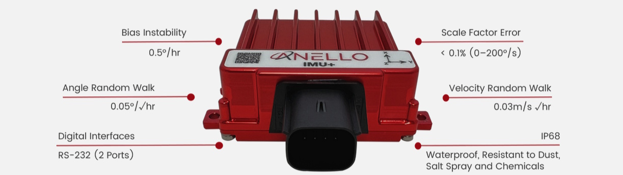
The ANELLO IMU+ (Source: ANELLO)
The ANELLO IMU+ offers high reliability and performance under harsh environments including shock, vibration, and thermal gradients. Its IP68 rating signifies the highest level of water and dust resistance available. You could drop it in a saltwater swimming pool and it would keep on working (unlike the machine to which it was attached, but at least you’d know where that machine was).
Why no GPS? Well, the IMU+ is intended for applications like industrial robots working in warehouses where GPS would be superfluous because they couldn’t detect it in the first place.
Next up are applications that demand an INS (Inertial Navigation System), which employs an IMU in conjunction with external correction in the form of GNSS (and/or other sensors) along with a CPU and algorithms to perform sensor fusion and process motion data. All of which leads us to the ANELLO GNSS INS.
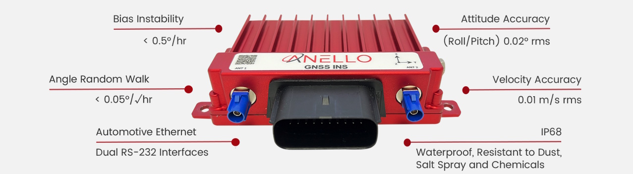
The ANELLO GNSS INS (Source: ANELLO)
Once again this contains one SiPhOG. It also contains two five constellation multi-band GNSS receivers and hardware PTP (Precision Time Protocol) time synchronization. And, once again, it also contains an ASIL-D CPU running an RTOS to control everything and to perform sensor fusion.
Moving on, we next have the ANELLO X3, which is the world’s smallest and lightest 3-Axis high performance optical gyroscope IMU. The ANELLO X3 leverages three state-of-the-art SiPhOG units as low-noise and low-drift optical smart sensors, each containing its own independent 6-axis redundant IMU (each of which has its own ASIL-D CPU).

The ANELLO X3 (Source: ANELLO)
The X3 doesn’t contain its own GNSS/GPS systems because it’s intended for use on things like drones that already have their own GNSS/GPS capabilities. The important thing here is that the X3 offers the same performance as its traditional FOG ancestors at 1/5 the size, 1/5 the weight, and 1/4 the power. Once again, I ask “What’s not to love?” (In this case, the answer’s a resounding “NOTHING!”)
Last, but certainly not least, we have the ANELLO MARITIME INS, which is like the X3 on steroids. In this case, in addition to everything offered by the X3, the MARITIME INS also includes dual triple-frequency GNSS receivers with static heading capability.
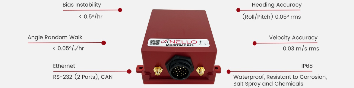
The ANELLO MARITIME INS (Source: ANELLO)
Powered by ANELLO’s advanced sensor fusion engine, the MARITIME INS delivers unparalleled precision and reliability for autonomous surface vessels (ASVs) and autonomous underwater vessels (AUVs).
Speaking of ANELLO’s advanced sensor fusion engine, this uses AI to provide state-of-the-art sensor fusion in conjunction with GNSS spoofing detection and mitigation.
As always, “the proof of the pudding is in the eating,” as they say. Let’s use agriculture as an example. Today’s precision agriculture demands accurate positioning and guidance for tractors. Look at the image below. This was taken in the fall. It involves spraying nasty chemicals in an orchard. The trees have leaves, the leaves contain water, and the water absorbs GNSS signals.
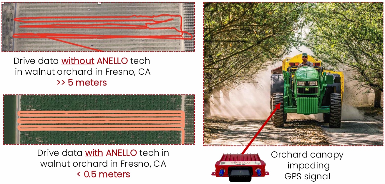
Test driving ANELLO GNSS INS in an orchard (Source” ANNELO)
The result using GPS alone is shown in the upper left. In this case, the error is >> 5 meters (that’s 16+ feet, Eeek!). By comparison, the result using GPS in conjunction with an ANELLO GNSS INS is shown in the lower left. In this case, the error is < 0.5 meters (that’s only ~1.5 feet). Just looking at the images, I know which system I’d want on my own tractor.
As an example of spoofing mitigation, consider the graphics below. These show the results of a land application equipped with an ANELLO GNSS INS being subject to spoofing attacks (the location is not shown because these tests took place in what we might call a sensitive situation).

ANELLO GNSS INS on a land application detects and rejects spoofing (Source: ANELLO)
A similar situation applies to drones equipped with their own GNSS accompanied by an ANELLO X3. If a typical drone’s autopilot detects loss of GNSS or a spoofing attempt, it is typically forced to execute a failure mode, such as hover in place, land, or self-destruct. By comparison, a drone equipped with an ANELLO X3 can automatically detect loss of GNSS or spoofing and use its highly accurate SiPhOG-based IMU to continue to its designation (target).
I don’t know about you, but I think we deserve to watch some videos: Navigating in GPS Denied Environments and ANELLO X3 Inertial Measurement Unit (IMU) On A Drone.
As I said at the beginning of this column, I learn something new every day. In this case, I now know more about inertial measurement units and inertial navigation systems—including optical gyroscopes and accelerometers—than I ever expected (or wanted). I wonder what tomorrow will bring. In the meantime, I also wonder if you have any thoughts you’d care to share on anything you’ve read here.


how can I download this materials PDF
To what “materials PDF” are you referring?