


You are now entering the “It can’t be done” zone. But, at least for the moment, I’ll ask that you relax that axiom, even if only slightly, to something less absolute, like “We’re pretty sure it can’t be done.”
That’s because we are approaching the Holy of Holies, Mystery of Mysteries, Most Unapproachable of That Which is Unapproachable: analog design automation.
Before we dive in, let’s set up the contrasts first by revisiting the highly automated world of digital design. Heck, digital designers practically don’t need to know what a transistor looks like. They can specify their logic in text format, send that into a toolchain, and voilà: a completed layout.
Yes, this process is heavily guided by constraints: timing and power and area constraints through one of the various formats that allow such specifications (SDC, UPF, etc.). The tools can take these statements of intent and use them to guide the creation of a layout that meets all of the constraints (assuming they can be met).
Of course, in reality, digital designers may need to iterate to optimize their circuits – sometimes at a level beneath RTL (although optimization at RTL was another topic raised at DAC; we’ll look at it in a future piece). But, in principle, and occasionally (and increasingly, given tool improvements), single-pass success can be achieved.
There are a few characteristics of digital design that make this possible:
- The figures of merit that must be satisfied are straightforward: power, speed, and area.
- We have standard digital cells. The tools aren’t smart enough to turn RTL into transistor circuits; cell designers manually craft circuit blocks (in a standard cell library or even as IP) and those simply replace text entities. Yes, there may be multiple versions of a particular circuit – different aspect ratios or speed/power levels, but at no point is the tool tweaking transistors; it’s selecting blocks and perhaps setting parameters.
- These capabilities have evolved over time; at each stage, designers grew to trust the tools and to accept automation as a legitimate way of generating quality circuits. Yes, you might be able to find ways to hand-pack things more tightly, but you’d never do it in time with a billion-gate circuit. A good-enough circuit today is far more useful than a super-optimized one in 20 years. In short, digital designers trust their tools enough.
None of these three has ever held for analog.
- “Performance” could refer to a variety of parameters, depending on the purpose of the circuit. Bandwidth, Q, signal-to-noise ratio – any number of specialized measures might act as the critical figure of merit for an analog circuit.
- Standard cells haven’t really been a thing in analog. We looked at a Stanford project to populate a library of analog standard cells almost two years ago; I just clicked the link to that library, and my browser could find no server at that location. (A Google search didn’t show anything promising, either.)
- Analog designers have been notoriously suspicious of tools that purport to do a better job than they themselves could do. Frankly, analog designers judge circuits both functionally and aesthetically. The aesthetics can often reflect desired behavior, so some circuits just “look” better than others; such aesthetics are hard to automate. We looked at a limited attempt towards helping automation when Cadence allowed low-level constraints that both the layout and simulation tools could understand, but that’s about as far as the automation got then. Everything else to date has failed, and this history of failure compounds designer distrust.
But that hasn’t stopped one company from trying. At DAC, Pulsic announced, amongst other things, a new tool called Animate that promises to do what prior tools haven’t been able to do: automate analog layout, using only the schematic and constraints as input.
The automation approach is somewhat different from that used for digital, as we’ll see, but the idea is that of a flow driven by high-level constraints that delivers laid-out blocks with quality approaching or equaling that which could be done by hand.
Looked at from a high-level flow perspective, here is how Pulsic describes the standard analog flow:
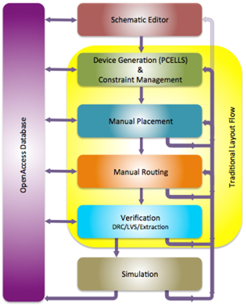
(Image courtesy Pulsic)
There are a number of items here to draw your attention to:
- Placement and routing are done manually.
- Placement is a separate step from routing and is done in advance of routing. This is traditional even in the digital world (and it kind of makes sense: it’s hard to create a route if you don’t know where the endpoints are yet).
- Verification involves ensuring that the layout matches the schematic (LVS) and that the layout passes DRC muster. Extraction is a final step, providing models for the follow-on simulation.
- There are numerous feedback loops here. You can end up iterating from almost anywhere to almost anywhere.
The end result is that of a laborious process that takes a long time to complete.
The approach that Pulsic is taking with Animate changes all of these. They’ve developed what they call “PolyMorphic” algorithms that do concurrent placement and routing. This constitutes much of their special sauce. With an underlying database and a novel architecture that they’re working on patenting, they somehow use routing info to optimize placement to optimize routing. Or something.
There are several important points about how this works:
- The tool generates multiple layouts.
- Each layout can be generated very quickly. As an example, they say that they could generate 200 different layouts from a 700-transistor schematic in about 1.5 minutes.
- As a result of the speed, the engine can be constantly running in the background such that, as you tweak the schematic or constraints, it immediately starts creating new layouts based on those changes.
- The layouts it creates are guaranteed to be DRC-compliant. They have their own DRC engine built in (although you can also hook to other DRC engines like Mentor’s popular Calibre tool). This means you don’t need a separate DRC/LVS verification step.
This results in a flow looking more like this:
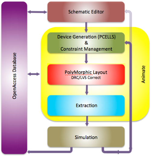
(Image courtesy Pulsic)
The manual steps have been replaced with a single automated step, and the verification is gone (extraction is still needed for simulation).
This isn’t quite the same as a digital flow because of the fact that multiple layouts are created. The designer can pick and choose the most desirable layout and move forward with it. This is an important distinction in that it still recognizes the fact that a designer may have layout expectations that can’t be expressed as constraints, so there’s no one single “best answer” that the tool can create. The designer makes the final call.
Now… given that the tool can generate hundreds to thousands of layouts, you might expect that your manual layout time would be replaced by the tyranny of too much choice: how the heck to decide which of 500-odd layouts to use. Kind of like trying to figure out which of 98,352 different Solitaire apps you should put on your phone.
Animate addresses this by using area as a primary figure of merit. It will select as its best result the layout with the lowest area, with a backup of the layouts that fell within 20% of the smallest area. This should limit the amount of browsing necessary to choose a result
Pulsic’s approach keeps a bit of “manual” in the automated flow, but, critically, it’s the laborious manual creation of layouts that disappears from the flow. And there’s another consideration: manual layout can result in one solution; a manual designer will not usually have the luxury of enough time to explore numerous different approaches. So, in theory, anyway, you may actually get a better solution via automation because you can explore more layouts.
Note also that the multiple feedback paths are gone. This is intended as an “unbreakable” flow. No getting into the middle of things and hand-tweaking the results. If you want something different, you change either the constraints or the schematic. Again, in theory, there shouldn’t be anything you want to do that can’t be expressed there.
For now, there’s not even a way to intervene manually without taking the layouts to another tool to hand-craft them. But that would be “breaking the flow,” and Pulsic’s intent is that you should never have to do that.
Despite such best intentions, one cannot avoid, of course, the inevitable dreaded engineering change order (ECO). That is, the last-minute change to fix a late-discovered bug or implement a late-inspired feature. While most automated flows run on the assumption that you shouldn’t break the flow by monkeying with the intermediate or final results, those flows also typically take too long to redo at the last minute – if for no other reason than it restarts the entire verification cycle. So the challenge and beauty of the ECO are that you make a narrow, targeted, (usually) low-level change, and everything else stays as it was. And hopefully your masks get made in time.
At present, there’s no way to accommodate ECOs and stay within the Animate flow. They are looking at a smart editor in the future that will accommodate changes without breaking the PolyMorphic modeling.
It’s also worth noting that numerous fussy aspects of analog design can be automatically detected and implemented. Things like common-centroid or mirror designs, guard rings, matching, and other such characteristics can be handled without scripting or programming.
The time savings that Pulsic claims come from two differences from standard manual flows. One is the obvious savings in manual layout time. The other is more subtle: with a manual flow, you want to smooth the layout process as much as possible, so you’re likely going to wait until your schematic is 80-90% or so done (Pulsic’s number) before handing it over to the layout designer.
By contrast, Animate can be started with something more like 40% completion, working on what’s there while you continue design. In other words, layout goes faster, but it also starts earlier. If the early parts of your design get laid out to your satisfaction, you can lock them down so that future layout work on the rest of the circuit doesn’t repeat or reverse that work.
In fact, early layouts can be used to help with floorplanning and other early architectural work, which, in theory, should result in a higher-quality finished product.
There’s been lots of “in theory” aspects in my descriptions of this tool, but that’s not to say that there’s another shoe about to drop showing why theory fails. It’s simply an overabundance of caution, given the spotty history of automated analog. I have no evidence that this all doesn’t work, but I have evidence only from Pulsic that it does work. Further results from designers will be the confirmation that, in fact, theory is reality. And whether, in fact, “it can’t be done” gets replaced by “someone finally did it.”
More info:


What do you think about Pulsic’s approach to automating analog circuit design?