


Well, it seems to be sensor hub season. A couple of interesting things are brewing. One, in particular, is of strategic significance, and I’ll be writing that up once I get a chance to dig into some more details.
For today, we’re going to go tactical rather than strategic: we’re going to dig deeper into QuickLogic’s sensor hub solution. And we’re going to get our hands dirty. If you read my earlier piece on sensor hub partitioning, you’ll recall that QuickLogic has a rather intricate implementation that puts much of the sensor hub functionality in FPGA hardware using a combination of low-level software, state machines, and outright hardware. Their claim is that they can achieve the lowest power this way – lower than a more common microcontroller implementation.
The challenge for this is, of course, that sensor hub functionality is largely expressed in software, and most software engineers aren’t going to have an easy time creating FPGA hardware. So it is a rather delicate dance that QuickLogic must do, abstracting hardware stuff to look like software and working hand-in-hand with customers as necessary.
They recently made a couple of announcements relative to their hub solution. First was the fact that they now claim to meet the requirements of the Android KitKat release, which we recently covered. They also announced the availability of what amounts to an IDE for doing sensor fusion design using their hub solution, which they call FFEAT (Flexible Fusion Engine Algorithm Tool), along with a dev board for use in getting sensor fusion software written and debugged.
This seemed to set up a good opportunity to look more closely into the environment that QuickLogic provides for software engineers to do what is essentially hardware design. This is, in my opinion, important, since good conceptual ideas often fail because they don’t meet the intended beneficiary on the right level. Even as a marketer, I’ve watched as people who were interested in a solution balked at the real-world nuts-and-bolts process they’d have to go through. And the risk of that is particularly high when hardware and software meet, with the two sides having very different assumptions and language.
I also see value here beyond simply delving into QuickLogic’s solution; hopefully the discussion will illuminate more general sensor hub issues.
Sensor Hubs 101
So let’s start out at the architectural level. QuickLogic provides the following simple image to illustrate the overall goal of the sensor hub. On the left is a pure old-school sensor solution, where the sensors are all connected to the application processor (AP) via, in this case, I2C. All of the sensor fusion functionality is then implemented in the sensor framework, making the sensor data available at the programming level (typically Java).
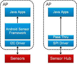
Figure 1. A sensor hub takes functionality away from the AP so that it can sleep. (Image courtesy QuickLogic)
On the right, by contrast, the sensor hub takes on much of the work that used to be done in the sensor framework on the AP. If the hub manages to suck everything down out of the AP, then all the AP has to do is talk to the hub (via what, in this case, is an SPI bus) and then simply pass the pre-digested data up to the app level, bypassing all of the other rigmarole in the AP.
As a result, the AP can sleep instead of having to deal with all the battery-burning sensor machinations at a low level. The hub does the low-level work while the AP sleeps, secure in the knowledge that, if something interesting comes up, the hub will wake the AP up to let it know. Sort of like the relationship between a President or Prime Minister and his/her advisors.
Daemon’s domain
The Android hardware abstraction layer (HAL) provides a way for applications to indicate which sensor events are of interest. It does this by registering them with… whatever is managing these events. QuickLogic’s architecture makes use of a daemon from Sensor Platforms to manage various sensor event queues, so it’s involved in this registration process.
You can register for simple events, like, say, rotation (we’ll look at rotation as an example in a minute, so might as well start with it here). Or, in theory, you could create more complex events, like “stopped running.” Presumably, with Android, you’d limit your registrations to events that the Android HAL understands.
In fact, if all you register for is rotation, then, no matter what other events the sensors might be able to generate, those won’t be of interest to the application (or else it would have registered them). So, for instance, if a “step” event occurs, the hub will decide, “OK, dude just took a step, but the app doesn’t care about that, so I’m not going to wake him up.” And the sensors may pout a bit, complaining that no one ever listens to them, but there’s not much they can do about it.
For registered events, the hub will post the event and data to the daemon via an interrupt and a “packet.” The daemon will then queue the event. The daemon could actually be managing a variety of different queues going to support, for instance, multiple applications, so when the interrupt occurs, it just means that the event goes onto the queue; it doesn’t guarantee an immediate response.
Once the hub has handed the packet off to the daemon, the hub is done and goes back to monitoring the world at the sensor level. The daemon will provide the data up to the application level in its own time and as the queues dictate. We won’t get into the detailed operation of the daemon in this piece (mostly because I don’t know those details); we’ll focus on the hub.
I’ve illustrated this relationship below. (Note that the remaining figures will look different here, since they’re my own; in case you or QuickLogic take issue with something, I want to be sure you yell at me and not at QuickLogic.)
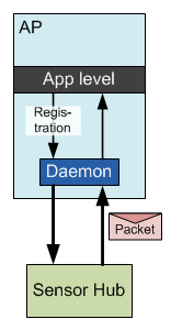
Figure 2. The sensor hub posts event packets onto a queue managed by the daemon.
It does bear noting, however, that a fair bit of further computing may happen in the daemon – in particular, context-awareness functions that update infrequently. So that innocuous-looking daemon box can hide a fair bit of functionality.
As a quick aside, QuickLogic sees the possibility of a microcontroller entering the picture here in the future, further offloading some of those daemon functions from the AP. My immediate response to that thought went as follows: we’re using a hardware-based hub here because it can operate at lower power than a microcontroller. If you have to add a microcontroller back in, haven’t you given up that benefit?
QuickLogic’s answer is, of course, “No.” They see this as a tiered approach: the always-on busy stuff will still happen in hardware with lowest power. Moderate-frequency stuff can happen in the microcontroller at lower power than the AP. So the hardware wakes the micro when it thinks something interesting has happened; the micro then does some more work, ultimately waking the AP if it agrees that the event is worthy of attention.
In this scenario, the micro does nothing else, so it gets to sleep and/or operate at a more relaxed pace than an over-taxed handle-everything micro, meaning that the overall power will still be less than what an all-micro solution would involve. As a reminder, this is NOT how things work today; there is no microcontroller in the solution we’re about to discuss.
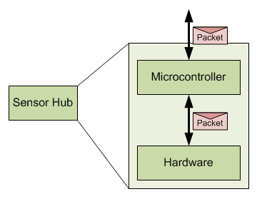
Figure 3. Speculative future architecture.
Note that we have different programming levels here. At the app level, we’re talking Java. If there were a micro, we’d be talking C/C++. At the hardware level, well, that’s where things get interesting.
The Kernel will see you now
Let’s drop down into the low-level QuickLogic paradigm. I’m not going to worry about the actual hardware structure (which I outlined in that prior piece); instead, I’m going to look at things in the way that a designer would. There are lots of grody bits that have been abstracted away by QuickLogic – which is critical to appealing to software engineers. (That’s not a slam; software folks have different grody bits to attend to.)
For instance, low-level interaction with an actual sensor is provided through a library and a basic sensor definition file. That simplifies the process of futzing with which register to read at what interval to get some piece of raw data.
The actual processing of sensor data happens via an engine or kernel (QuickLogic hasn’t used this word to describe it, but I use it because I find it suitably evocative) that wakes and sleeps under the control of a small timer that remains awake (think of the timer as a mini-daemon). When nothing is going on, the timer is the only thing running – the clocks for the rest of the hardware are literally shut down. Only when the timer says it’s time to do some work does the kernel wake up and draw power.
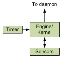
Figure 4. Conceptual picture of QuickLogic sensor processing.
Each time the kernel wakes up, some work will get done. That typically means sampling one or more sensors to get new values and then running some algorithm to see if anything of interest has occurred. If not, then the kernel goes back to sleep until reawakened by the timer. If something interesting has happened, then that data is sent on to the AP before the kernel goes to sleep.
Note that by “interesting,” I’m referring to an event that has been registered by an application as being of interest. If the application wants to know about rotations, then, as we’ll see, you calculate the rotation when it changes and send on the new data.
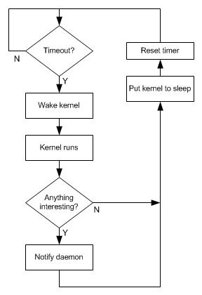
Figure 5. Conceptual illustration of how the timer manages the algorithms in the kernel.
The kernel is where the designer does his or her low-level magic. The timer, the sensor access – all of that is hidden away from hesitant or mischievous hands.
(I should emphasize here that these are my interpretations of how this works. It shouldn’t be mistaken as representing to the letter how QuickLogic would specifically describe it; you would need to consult their documentation for the official word. I’m pretty confident in the broad strokes; some details may vary – for instance, I wouldn’t swear to the literal accuracy of the flowchart, but it illustrates the point.)
Some setup code
The algorithm is where we’ll spend our time now. QuickLogic provides a simple language for writing the algorithms; it’s a relatively readable approach, so code snippets can be illustrative. And we’ll use rotation as an example – that’s what QuickLogic’s Tim Saxe took me through.
In order to promote portability, QuickLogic segments the code in two: a “sensors” sector and an “algorithms” sector. This allows swapping of different specific sensors: any sensor-specific stuff happens in the sensor segment, while the algorithms can remain unchanged. The two segments are “joined” by an “FFEVariable.” This is essentially an object that receives sensor data on the sensor side of the divide and is read by the algorithms on the algorithm side.
Figure 6. Sensor specifics are abstracted from the algorithms, passing through an FFEVariable
There’s nothing intrinsic about FFEVariable, by the way; it’s defined as a structure in the code, consisting of the actual sensor data and the scaling factor (which will vary by sensor):
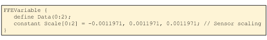
Figure 7. Code snippet defining FFEVariable. (Code courtesy QuickLogic)
The sensor side largely defines properties specific to whichever sensors are attached. Some example abridged code is shown here for an InvenSense gyro, illustrating some definitions and behaviors. I’m not going to dive in more deeply.
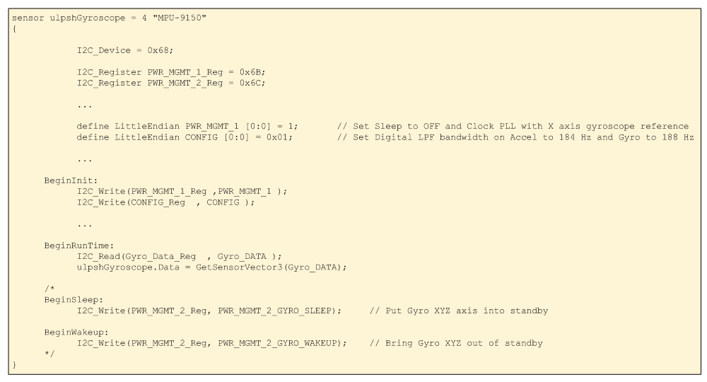
Figure 8. Sensor definition code snippets.
(Click image to enlarge. Code courtesy QuickLogic.)
Meanwhile, on the backend of things, each event gets a packet defined according to the data expected by the AP. Here I show two related packets: one for raw gyroscope data and the other for rotation data. The first delivers three data points (one per axis); the other delivers a full quaternion.
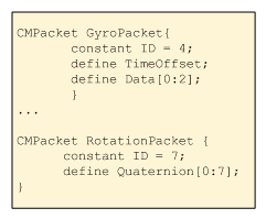
Figure 9. Packet definitions (Code courtesy QuickLogic)
Filling the pipeline
So what about the algorithm itself? Before we go too deep, there’s an important characteristic to note about the engine – the sort of thing that may be more obvious to a hardware guy. The engine uses a pipeline with two stages.
For folks that aren’t familiar with pipelines, they’re a really useful way of providing parallel behavior because each stage does some simple thing and passes the result on to the next stage. While the second stage starts work on whatever it just got, the first stage can start on some new data. It takes a few cycles to get the first data though the pipeline, but, once the pipeline is full, you get new data every cycle.
The way this works with QuickLogic’s hub is that, with each cycle, you do a read and a write at the same time through the magic of hardware parallelism. Specifically, the compiler schedules a data read one cycle ahead of when it’s needed for an assignment. While this may provide some performance benefit, it can occasionally get you in trouble if you end up trying to read and write to the same location at the same time – the compiler will complain.
The good news is that, for the most part, you don’t need to know about this. You write your algorithm and the compiler packs it into the pipeline. But it’s not completely transparent. On those occasions when the compiler complains, you may have to add an NOP operation to force the system to serialize a read and a write rather than trying to do them in parallel. Alternatively, you may need to think explicitly about instruction ordering.
In the following figure, Var1 is involved in an assignment to Var2. So in the first cycle, Var1 is read; the assignment to Var2 happens in the next cycle. At the same time, Var4 is read in preparation for the next Var3 assignment. Then, when Var3 is assigned, it also tries to read in preparation for the Var5 assignment, but that involves reading Var3, which is currently being written. So that would be flagged as a problem by the compiler, and a NOP would be needed to give the write a chance to finish before the read happens.
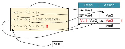
Figure 10. A pipeline architecture requires some attention to simultaneous reads/writes.
With all this background, then, the algorithm is relatively straightforward. We’re going to use the gyroscope data to determine the new rotation position based on any rotation that’s happened since the last time we ran through all this. That means we need to know the new gyro data and how long it’s been since the last check-in.
- The raw gyroscope data is first scaled into MKS units.
- We then figure the rate of rotation;
- From that we can get an absolute amount of rotation, and
- Adding that rotation to the old position gives the new position. (“Position” used loosely here, since we’re talking only rotation, not linear translation.)
- We then normalize the rotation (which scales it to give it magnitude to 1; this apparently is standard and helps to avoid drift eventually causing over- or underflow).
- We write the rotation packet, and
- Send it off as an interrupt.
The code that does this is shown below.
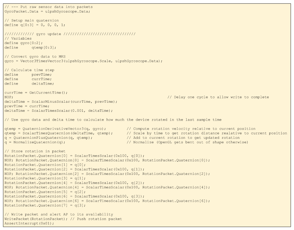
Figure 11. Rotation algorithm code.
(Click image to enlarge; code courtesy QuickLogic)
Library additions
All of those quaternion functions are pre-defined in a library, so that’s done for you. How do they decide what to put in the library? Well, the philosophy is to include anything that’s likely to be needed repeatedly by one or many customers. Quaternion math certainly fits that category.
QuickLogic is pretty flexible, though. In fact, I got to see their philosophy in action. When they showed me this code, normalization was explicitly shown using the code below. During the discussion, Mr. Saxe thought that this is a common enough function to merit addition to the library. That way they can optimize how it works (it involves more than a few NOPs, for example) and raise the level of abstraction for programmers. The current code as shown above reflects this improvement.
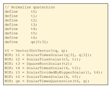
Figure 12. Normalizing a quaternion (Code courtesy QuickLogic)
Resolving simultaneous reads and writes
The time calculation provides a good example of the NOP thing. First, currTime is determined; next, deltaTime is calculated based on currTime. The first is an assignment; the second is a read. If they simply followed one after another, then the compiler would be unhappy because the read would be scheduled along with the write. So to separate those out, the NOP is inserted to force the assignment to happen first. Then the read can proceed without further ado.
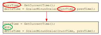
Figure 13. A NOP provides a chance for assignment to complete before the value is read.
Meanwhile, the next two instructions look innocuous, but the order matters. The time in the above code is in “ticks,” but ultimately, it has to be delivered in time units. So we need to scale the deltaTime variable. We also need to update prevTime. But we need to make sure that, when we’re scaling deltaTime, we don’t interfere with its write in the prior instruction.
The following figure illustrates the issue if we have the two deltaTime instructions back-to-back. There are two ways to resolve it: either add a NOP or reorder the following two instructions. There’s no conflict between assigning deltaTime and updating prevTime, and there’s no conflict between updating prevTime and scaling deltaTime. So this reordering provides a more efficient solution, requiring fewer cycles.
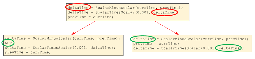
Figure 14. Need either NOP or instruction reordering to resolve simultaneous read/write.
(Click image to enlarge)
All of this code, then, compiles into the various hardware structures within the QuickLogic architecture. Aside from the NOP thing, it seems to do a pretty reasonable job of hiding the hardware.
That gives you a flavor for how this works. I could spend some cycles on the dev board as well, but that’s relatively obvious, and I’ve kept you here far too long already.
So, just to summarize, then, we’ve looked at how QuickLogic presents its sensor hub solution to software engineers, even though the solution is inherently a hardware one. Whether it strikes the right balance in exchange for power savings will determine the solution’s success.
More info:


What do you think about QuickLogic’s approach to making hardware accessible to sensor fusion software folks?